MODELS OF YV RPO 107 HAVE BEEN AVAILABLE IN BRASS FROM SEVERAL BUILDERS over the years in both HO and O scale. It is now also available as a resin kit from Southern Car & Foundry. This kit is primarily aimed at Southern Pacific RR modelers but includes a couple of details specific to the YV and builds into an impressive model of YV 107.
The prototype RPO (railway post office) car still exists today as part of the collection of the Pacific Locomotive Association in Fremont, CA. This webpage provides information in the form of a "walk-around" of the prototype in addition to some photos of the SC&F kit. The information can also aid in detailing one of the HO imported brass models or the O scale kit.
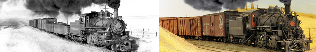
This photo was taken by Bob Lunoe in 1942 and shows the "left side" of the car. RPO cars were operated with the postal section (with the small "person" door) toward the locomotive and the baggage end closest to the rest of the train. There was a partition with a door between the postal and baggage sections of the car; this door was locked all of the time the car was in operation. By having the baggage end of the car oriented toward the rear of the train, a YV conductor could, if needed, access the baggage compartment for a passenger while the train was in motion. Note the battery box on this side of the car. The forward end of this box was lined up with the forward edge of the window above it. This battery box was smaller than ones used on SP cars and this optional detail is included with the SC&F O scale kit.Another view of the left side of the car. Note the horizontal "bars" on the first window behind the person door and the vertical bars on the other two windows. The horizontal bars are in the postal section of the car; the partition between the baggage and postal section was just forward (left) of the middle window.The rear end of the car with its ratchet style brake handle. This would be the B end of the car (the end with the "B"rake).The right side of the car. Note that while the car retained the safety bar across the postal door, there was no mail hook on either side of the car while in operation on the YV.Unique to the YV RPO car was the Baker Heater expansion tank mounted on the roof and the adjacent smoke stack for the Baker Heater. This is a close-up of the tank. The tank has what might be pressure safety valves on the top of the tank and possibly filler valves attached to the front of the tank. A casting replicating the Baker Heater expansion tank is included with the SC&F O scale kit but not the stack. I sell HO castings for the expansion tank (from a SC&F master).This and the following views are of the car on the Pacific Locomotive Association's Niles Canyon Railway circa Summer 2009 . While the lettering is representative of the prototype, it is not entirely accurate (my O scale and HO scale decals are accurate for the car while it was in service on the YV). This is a wide-angle view of the right side of the car coupled to YV Observation 330 on the left.A close-up of the rear of the car.A head-on view of the baggage door.The Baker Heater expansion tank was located above this window. The smoke stack to the left of this window is not the stack used when the car was in service on the YV.One of the windows on the right side of the car and the mail "person" door. The window frames were painted brown while on the YV. The YV car was painted in a version of "Pullman Green" which was not as brown as the car these days.A close-up of the mail "person" door. Note that the car did not have mail hooks while in operation on the YV. The hook on this side of the car is also mounted "backwards" since the car was normally operated with the mail section forward.A close-up of a ladder rest and a regular grab iron on the B end of the roof. This view also shows the vent on the centerline of the car.The A end of the car. To the left of the door is the retainer valve. Although missing on the car today, this end also had a regular diaphragm as did the opposite end. Note that the vent on the centerline of the car and the stove stack to the right were not in place when the car was operated on the YV. The horizontal grab irons halfway up the end of the car were also not there while the car was in operation on the YV.The left side of the car today. I think that the smoke stack was added by the V&T after the Baker Heater was removed. While being used as a postal car, there was a mail drop just to the right of the word "MAIL"...it has been covered over but shows up in the B/W prototype photos. If you mailed a letter via this mail drop, it would be canceled with a rubber stamp listing the date, train number, and the initials "RPO".A close-up of the left side of the forward end of the car.The defect car holder. Note how the grab iron next to the baggage door curves up before turning down. This is typical of the side grab irons on the car.The brake handle on the B end of the car which was also the baggage end of the car. A.D. Shader scrapped the YV and sold the car to the Virginia and Truckee Railroad. Five years later, he scrapped the V&T and ended up keeping the car to use as an office. The air pipe to the right of the brake handle was probably added when the car was used as an office by A.D. Shader; it was not on the car while it was in service on the YV.A close-up of the coupler and uncoupler lever.Another view of the coupler. This view also shows how the brake hose was mounted.A straight on view of one of the trucks on the car.A close-up of one of the truck safety chains.Another view of one of the truck safety chains.This photo provides a good view of one of the step mountings as well as another view of the uncoupler lever. Note that it is a bottom-operated uncoupler lever.I've prepared a drawing of the underbody which can help identify the various brake parts in this and the following photos of the brake parts. Above is a close-up of the dust collector (reddish color), triple valve (behind it), and a portion of the brake cylinder on the right.Another view of the same general area showing some of the piping.A view of the brake cylinder. Note how this side of the cylinder is mounted to a steel bracket bolted to the underframe. The other side of the brake cylinder bolted directly to the pair of I-beams which formed the center beam.Looking slightly toward the B end of the car and the small air tank. The pair of lightly rusted pipes above the small air tank were not on the car during service on the YV and were most likely added by A.D. Shader when the car was used as an office.The hand brake lever with the chain which connects it to the slotted crosshead. The opposite end of the hand brake connected to a rod which connected to the hand brake. The piping with the pair of elbows is part of the modifications by A.D. Shader.A view of the same area from the opposite side of the car. The rod with the clevis attached to the hand brake lever which in turn connects to a chain which then connects to the hand brake.Looking toward the large air tank on the opposite side of the car with the brake lever hangers in the foreground. The brake cylinder is barely visible beyond the hangers. The aluminum electrical conduit and electrical cord are from when the car was being used as an office by A.D. Shader.Looking slightly toward the B end of the car from the previous photo. Both brake levers are visible in this photo. The rod to the hand brake is angling back over the truck and toward the rear corner.This view shows the end of the hand brake rod. A hook connects it to a chain which passes around a horizontal pulley and then around a vertical pulley where it connects to the hand brake spool inside the rear wall. The chain hanging down is one of the truck safety chains.A closer look at the brake lever closest to the B end of the car. Above the clevis is the main brake pipe and the tee to the brake cylinder. This tee is not visible in the drawing of the underbody since it is obstructed by the brake lever.A good view of the brake hanger and brake lever and its connection to the slack adjuster. This view also shows how the triple valve is bolted to the bottom of the brake cylinder.Looking up at the coupler.The car is currently being used as storage for tools and materials needed for the restoration of YV Observation 330 which is coupled to the 107. This view looks toward the postal section from the baggage section. Note the roof vents in the ceiling.This view looks forward in the postal section. The large hole above the window is where the stack for the Baker Heater was located.
SOUTHERN CAR & FOUNDRY RELEASED AN O SCALE RESIN KIT for a Harriman 40' RPO car in mid-2009 which can be assembled, painted, and lettered for the Yosemite Valley Railroad. Here are photos of my completed O scale model of YV 107 using this kit.
The right side of the car.The left side of the car. I added a number of additional details to the basic kit including the valves on the Baker heater expansion tanks, the unique smoke stake behind the tanks, uncoupler levers, truck safety chains, door safety bars, and window protection bars.A close-up of the baggage door area and air reservoirs. Note the brown window sashes and fine rivet detail of the resin casting.The rear end of the car.The forward end of the car. Note that all of the grab irons, steps, hand brake, and door safety bar were painted black on the prototype.A close-up of the Baker Heater expansion tank and smoke stack.The truck safety chains. Since this is a display model (rather than an operating model), I replaced the wimpy truck springs with new springs formed from copper wire wound around a brass rod.The SC&F kit includes all of the parts needed to completely detail the underbody.Here is a close-up of the main brake components. The drawing of the underbody has the same orientation as this close-up which can help identify the various brake parts.